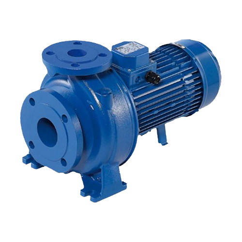
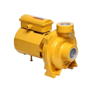
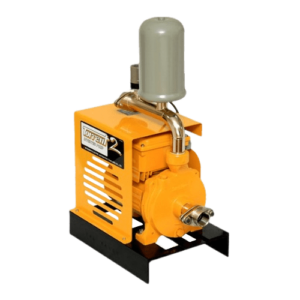
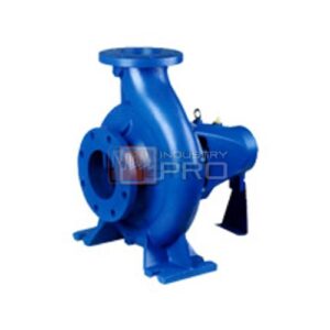
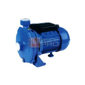
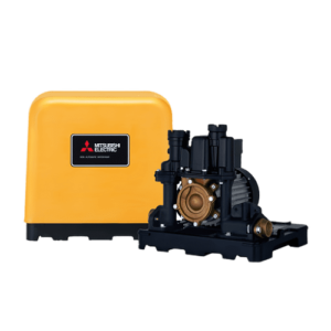
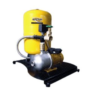
ปั๊มน้ำหอยโข่ง EBARA 3D Series
** M = 220V.
การใช้งาน
- อุตสาหกรรม: เหมาะสำหรับการใช้งานในโรงงานอุตสาหกรรมที่ต้องการการส่งน้ำที่มีปริมาณมากและแรงดันสูง เช่น การระบายความร้อนในเครื่องจักร การล้างเครื่องจักร และการจัดการน้ำในกระบวนการผลิต
- การเกษตร: ใช้ในการชลประทานและการจัดการน้ำในฟาร์มและสวน
- การใช้งานทั่วไป: เหมาะสำหรับการใช้งานในระบบน้ำประปา การเพิ่มแรงดันน้ำในอาคารสูง และการใช้งานในพื้นที่ที่ต้องการการจ่ายน้ำที่มีประสิทธิภาพสูง
SPECIFICATIONS
2 Pole
| MOTOR | ||||
| Type | 3D | 3DS | 3DP | |
| Electric – TEFC | ||||
| Single Phase | Three Phase | |||
| Efficiency (Reg. 640/2009) | – | IE2from 1.1 kW to 5.5 kW IE3 from 1.1 kWto22 kW | ||
| No. of Poles | 2 | |||
| Rotation speed [min1] | -2900 | |||
| Insulation Class | F | F (temperature rise class B) | ||
| Protection degree | IP 55 | |||
| Power rating [kW] | 1.1 + 2.2 | 1.1 +22 | ||
| [HP] | 1.5 + 3 | 1.5 + 30 | ||
| Frequency [Hz] | 50 | |||
| Voltage [V] | 230 ±10% | 230/400 ±10% (up to 4 kW) 400/690 ±10% (5.5 kW and above) | ||
| Capacitor | Built in | • | ||
| Over load protection | Provided by the user | |||
| Casinq material | Aluminium | |||
| Motor support | Cast iron / Aluminium | |||
| Dimensions of cable entry | M20X1.5 | PG 13.5, PG 16. PG 21, | M32X1.5, M40X1.5 | |
| M20X1.5, M25X1.5 | ||||
| Flange mount (IEC motor) | / | IM B5 (up to 2.2 kW) IMB35 (3.0 kW and above) | IM B3 | |
| PUMP | ||
| Liquid Handled | Type of liquid | Clean water |
| Working temperature * 1 | min. -5 max. +120 For full details see section “FLUID TEMPERATURE RANGE” on pag. 307 | |
| Maximum working pressure [MPa] | 1 | |
| Construction | Impeller | Closed centrifugal type for 32. 40, 50 version Reinforced laser welding for 40-200/1.5, 50-200/2.2 Closed centrifugal three dimensional blades for 65 |
| Shaft seal type | Mechanical seal | |
| Beanng | Bearing with contact seal | |
| Pipe Connection | Suction | Flange DN 50. 65 according to EN 1092-2 Flange DN 80 according to UNI 2236-67 (4 holes) |
| Discharge | Flange DN 32. 40. 50. 65 according to EN 1092-2 | |
| Material | Casing | Cast iron EN-GJL-250-EN 1561 |
| Impeller | EN 1.4301 (AISI 304) – 32. 40. 50 series EN 1.4401 (AISI 316) made by precision casting – 65 series | |
| Shaft seal | Ceramic/Carbon/NBR (see Optionals on pag. 306-307) | |
| Shaft / Coupling | EN 1.4301 (AISI 304) (wet extension) | |
| Bracket | Aluminium/Cast iron | |
| Accessory | Counterflange | DN 32. 40. 50. 65. 80 (see pag. 311) |
| Applicable standard of test | ISO 9906:2012-Grade 3B | |
32 size
| Pump type | l/min 0 | 100 | 150 | 200 | 250 | 300 | 333 | 360 | 400 | 450 |
| maAi 0 | 6 | 9 | 12 | 15 | 18 | 20 | 21,6 | 24 | 27 | |
| 32-125/1.1(M) ’ | 23 | 22.4 | 21.2 | 19.3 | 17.1 | 14.4 | 12.5 | – | – | – |
| 32-160/1.5(M) ’ | 28,5 | 27.5 | 25.9 | 23.7 | 21,3 | 18.5 | 16.4 | – | – | – |
| 32-160/2.2(M) ’ | 36.7 | 35.4 | 34,1 | 32,2 | 29.8 | 27,3 | 25,5 | – | – | – |
| 32-200/3.0 | 44 | 43 | 41 | 39 | 36.5 | 33 | 31 | – | – | – |
| 32-200/4.0 | 53 | 52.5 | 51 | 49 | 46 | 43 | 41 | 39 | – | – |
| 32-200/7.5 | 68 | 67 | 65 | 63 | 61 | 57 | 55 | 53 | 50 | 46 |
40 size
| Pump type | l/min | o | 200 | 250 | 300 | 350 | 400 | 450 | 500 | 600 | 700 |
| ma/h | o | 12 | 15 | 18 | 21 | 24 | 27 | 30 | 36 | 42 | |
| 40-125/1.5(M) ’ | 19 | 18.2 | 17.6 | 16.8 | 15.9 | 14.8 | 13.7 | 12.4 | 9.6 | 6.3 | |
| 40-125/2.2(M) ’ | 25 | 24.4 | 23.9 | 23.2 | 22.4 | 21.4 | 20.4 | 19.2 | 16.5 | 13.7 | |
| 40-160/3.0 | 31 | 29.4 | 28.7 | 27.8 | 26.8 | 25.8 | 24.8 | 23.7 | 21.4 | 18.7 | |
| 40-160/4.0 | 38,8 | 37.2 | 36.5 | 35.7 | 34.8 | 33.8 | 32.8 | 31.8 | 29.5 | 27 | |
| 40-200/5.5 | 45.5 | 44.5 | 44 | 43 | 42 | 41 | 40 | 39 | 36.3 | 33 | |
| 40-200/7.5 | 55 | 53,5 | 53 | 52 | 51,5 | 50.5 | 49.5 | 48.5 | 46 | 43 | |
| 40-200/11 | 71 | 70 | 69 | 68.5 | 67,5 | 67 | 66 | 65 | 63 | 60 | |
50 size
| Pump type | l/min 0 | 400 | 500 | 600 | 700 | 800 | 900 | 1000 | 1100 | 1200 |
| ma/h 0 | 24 | 30 | X | 42 | 48 | M | 60 | 66 | ||
| 50-125/2.2(M) ’ | 19.5 | 18 | 17 | 15.7 | 14,2 | 12.6 | 10,9 | 9 | – | – |
| 50-125/3.0 | 22,5 | 21.5 | 20.8 | 19.8 | 18,5 | 17,1 | 15,5 | 13,8 | 12 | 10 |
| 50-125/4.0 | 26.5 | 25.8 | 25.3 | 24.5 | 23.5 | 22.2 | 20.7 | 19 | 17.2 | 15,3 |
| 50-160/5.5 | 33 | 32 | 31.5 | 30.5 | 29.3 | 27.9 | 26.2 | 24.4 | 22.4 | 20 |
| 50-160.7.5 | 39.5 | 38.2 | 37.6 | 36.9 | 35.8 | 34.5 | 32.9 | 30.9 | 28.9 | 26,7 |
| 50-200/9.2 | 51.5 | – | 49.5 | 48 | 46.5 | 44.5 | 42.5 | 40 | 37.6 | 34.4 |
| 50-200/11 | 57.5 | – | 55.5 | 54.5 | 52.5 | 51 | 49 | 47 | 44.5 | 42 |
| 50-200/15 | 71 | – | 69,5 | 68.5 | 67 | 65.5 | 63,5 | 61,5 | 59 | 56 |
65 size
| Pump type | l/min | o | 600 | 700 | 1000 | 1300 | 1600 | 1900 | 2100 | 2200 | 2300 |
| ma/h | 4 | 36 | 42 | 60 | 96 | 114 | 126 | 132 | 138 | ||
| 65-125/4.0 | 22 | 20,4 | 19,8 | 17.2 | 14 | 10,4 | 6 | – | – | ||
| 65-125/5.5 | 26 | 25 | 22.5 | 19,4 | 15.5 | 11 | 8 | – | – | ||
| 65-125/7.5 | 31 | 29.6 | 27.5 | 24.7 | 21.5 | 17.8 | 14.7 | 13 | – | ||
| 65-160/7.5 | 31,6 | 29 | 26.6 | 23.5 | 19.8 | 15.5 | 12.3 | – | – | ||
| 65-160/9.2 | 36.5 | 34.7 | 32.4 | 29.6 | 26.3 | 22.2 | 18.8 | 17 | – | ||
| 65-160/11 | 40.5 | 39 | 37 | 34 | 31 | 27 | 23 | 22 | 20 | ||
| 65-160/15 | 48 | 46 | 44 | 41.5 | 38,4 | 34.6 | 31.9 | 30,5 | 29 | ||
| 65-200/15 | 54 | 51 | 47 | 43 | 38,6 | 33,3 | 29,2 | 27 | – | ||
| 65-200/18.5 | 60 | 58 | 55 | 51 | 47 | 41.5 | 37,9 | 35,9 | 33,6 | ||
| 65-200/22 | 68 | 65,5 | 62.5 | 58,5 | 54,5 | 49,5 | 46 | 44.5 | 42.5 | ||
4 Poles
| MOTOR | ||||
| Type | 3D4 | 3DS4 | 3DP4 | |
| Electnc – TEFC | ||||
| Three Phase | ||||
| Efficiency (Reg. 1781/2019) | IE2 from 0.25 kW up to 0.55 Kw IE3 from 0.75 kW up to 3.0 kW | |||
| No. of Poles | 4 | |||
| Rotation speed [min1] | =•1400 | |||
| Insulation Class | F (class B for temperature rise) | |||
| Protection degree | IP 55 | |||
| Power rating | [kW] | 0.25 + 3 | ||
| [HP] | 0.33 + 4 | |||
| Frequency [Hz] | 50 | |||
| Voltage [V] | 230/400 ±10% | 230/400 ±10% | ||
| Over load protection | Provided by the user | |||
| Casing material | Aluminium | |||
| Motor support | Cast Iron – Aluminium | |||
| Dimensions of cable entry | PG11, PG13.5, PG16 | M 10×15. M20x1.5. M25x1.5 | ||
| Flange mount (IEC motor) | / | IM B5 (upto 1.5 kW) IM B35 (2.2 kW and above) | IM B3 | |
| PUMP | ||
| Liquid Handled | Type of liquid | Clean water |
| Working temperature * 1 | min. -5 max. +120 For full details see section “FLUID TEMPERATURE RANGE” on pag. 307 | |
| Maximum working pressure [MPa] | 1 | |
| Construction | Impeller | Closed centrifugal type for 32. 40, 50 version Reinforced laser welding for 40-200/1.5, 50-200/2.2 Closed centrifugal three dimensional blades for 65 |
| Shaft seal type | Mechanical seal | |
| Beanng | Bearing with contact seal | |
| Pipe Connection | Suction | Flange DN 50. 65 according to EN 1092-2 Flange DN 80 according to UNI 2236-67 (4 holes) |
| Discharge | Flange DN 32. 40. 50. 65 according to EN 1092-2 | |
| Material | Casing | Cast iron EN-GJL-250-EN 1561 |
| Impeller | EN 1.4301 (AISI 304) – 32. 40. 50 series EN 1.4401 (AISI 316) made by precision casting – 65 series | |
| Shaft seal | Ceramic/Carbon/NBR (see Optionals on pag. 306-307) | |
| Shaft / Coupling | EN 1.4301 (AISI 304) (wet extension) | |
| Bracket | Aluminium/Cast iron | |
| Accessory | Counterflange | DN 32. 40. 50. 65. 80 (see pag. 311) |
| Applicable standard of test | ISO 9906:2012-Grade 3B | |
32 size
| Pump type | kW | HP | l/min 0 | 50 | 100 | 150 | 175 |
| rrf’/h 0 | 3 | 6 | 9 | 10.5 | |||
| 32-125/0.25 | 0.25 | 0.33 | 5.7 | 5.5 | 4.7 | 3.5 | 2.8 |
| 32-160/0.37R | 0.37 | 0.5 | 7.3 | 7 | 6.2 | 5 | 4.2 |
| 32-1600.37 | 0.37 | 0.5 | 9 | 8.7 | 8.1 | 7 | 6.3 |
| 32-200/0.55R | 0.55 | 0.75 | 10.8 | 10.3 | 9.2 | 7.3 | 6.2 |
| 32-2000.55 | 0.55 | 0.75 | 12.5 | 12 | 11 | 92 | 8 |
| 32-200’0.75 | 0.75 | 1 | 17.5 | 17.1 | 16.1 | 14.3 | 13.2 |
40 size
| Pump type | kW | HP | l/min 0 | 100 | 150 | 175 | 200 | 250 | 300 | 350 |
| rrP.’h 0 | 6 | 9 | 10.5 | 12 | 15 | 18 | 21 | |||
| 40-125/0.37R | 0.37 | 0.5 | 5.1 | 4.8 | 4.5 | 4.3 | 4 | 3.4 | 26 | 1.8 |
| 40-125/0.37 | 0.37 | 0.5 | 6.5 | 6.3 | 6 | 5.8 | 5.5 | 4.9 | 4.2 | 3.4 |
| 40-160’0.55R | 0.55 | 0.75 | 7.7 | 7.3 | 6.9 | 6.6 | 6.3 | 5.7 | 5 | 4.3 |
| 40-160’0.55 | 0.55 | 0.75 | 9.1 | 8.6 | 8.1 | 7.8 | 7.5 | 6.9 | 6.2 | 5.4 |
| 40-200’1.1R | 1.1 | 1.5 | 11.6 | 11.2 | 10.8 | 10.5 | 10.1 | 9.4 | 8.6 | 7.8 |
| 40-200’1.1 | 1.1 | 1.5 | 13.6 | 13.2 | 12.7 | 12.4 | 12.1 | 11.4 | 10.6 | 9.6 |
| 40-200’1.5 | 1.5 | 2 | 18 | 17.7 | 17.3 | 17.1 | 16.8 | 16.1 | 152 | 14.2 |
50 size
| Pump type | kW | HP | l/rrin 0 | 200 | 250 | 300 | 350 | 400 | 500 | 600 | 650 |
| rr?/h 0 | 12 | 15 | 18 | 21 | 24 | 30 | 36 | 39 | |||
| 50-1250.55R | 0.55 | 0.75 | 5.4 | 5.2 | 5 | 4.7 | 4.4 | 4 | 3.2 | 2.3 | – |
| 5O-12SD.55 | 0.55 | 0.75 | 6.4 | 6.2 | 6 | 5.7 | 5.4 | 5 | 4.2 | 3.3 | – |
| 50-160’1.1R | 1.1 | 1.5 | 8.2 | 7.8 | 7.6 | 72 | 6.9 | 6.4 | 5.5 | 4.5 | 4 |
| 50-160’1.1 | 1.1 | 1.5 | 9.5 | 9.1 | 8.9 | 8.6 | 8.3 | 7.9 | 7 | 6 | 5.5 |
| 50-200’1.5R | 1.5 | 2 | 12.7 | 121 | 11.8 | 11.4 | 11 | 10.5 | 9.3 | 8 | 7.2 |
| 50-200’1.5 | 1.5 | 2 | 14 | 13.3 | 13 | 127 | 122 | 11.8 | 10.6 | 9.2 | 8.4 |
| 50-200’2.2 | 2.2 | 3 | 17.8 | 17.5 | 17.3 | 17 | 16.6 | 16.2 | 15.1 | 13.8 | 13.1 |
65 size
| Pump type | kW | HP | l/min 0 | 300 | 350 | 500 | 600 | 800 | 950 | 1000 | 1050 | 1100 | 1200 |
| rrf.’h 0 | 18 | 21 | 30 | 36 | 48 | 57 | 60 | 63 | 66 | 72 | |||
| 65-125/0.55 | 0.55 | 0.75 | 5.3 | 4.8 | 4.6 | 4 | 3.5 | 2.3 | 1.4 | – | – | – | – |
| 65-125/0.75 | 0.75 | 1 | 6.4 | 6 | 5.8 | 52 | 4.6 | 3.5 | 25 | 2.2 | – | – | – |
| 65-125/1.1 | 1.1 | 1.5 | 7.7 | 7.2 | 7 | 6.3 | 5.7 | 4.5 | 3.5 | 3.2 | 2.8 | – | – |
| 65-160/1.1 | 1.1 | 1.5 | 8.6 | – | 8.1 | 7.4 | 6.9 | 5.7 | 4.6 | 4.2 | 3.8 | – | – |
| 65-160/1.5 | 1.5 | 2 | 9.7 | – | 9.2 | 8.5 | 8 | 6.7 | 5.7 | 5.3 | 4.9 | 4.5 | – |
| 65-160/2.2 | 2.2 | 3 | 11.8 | – | 11.3 | 10.6 | 10.1 | 8.8 | 7.6 | 7.2 | 6.8 | 6.4 | 5.5 |
| 65-200/2.2R | 2.2 | 3 | 13 | – | 12.4 | 11.6 | 10.9 | 9.3 | 78 | 7.3 | 6.8 | – | – |
| 65-200/2.2 | 22 | 3 | 14.5 | – | 13.9 | 13 | 12.4 | 10.8 | 9.3 | 8.8 | 8.3 | 7.8 | – |
| 65-200/3 | 3 | 4 | 16.3 | – | 15.8 | 15.1 | 14.4 | 12.9 | 11.6 | 11.1 | 10.6 | 10.1 | 9 |
